
Introduction
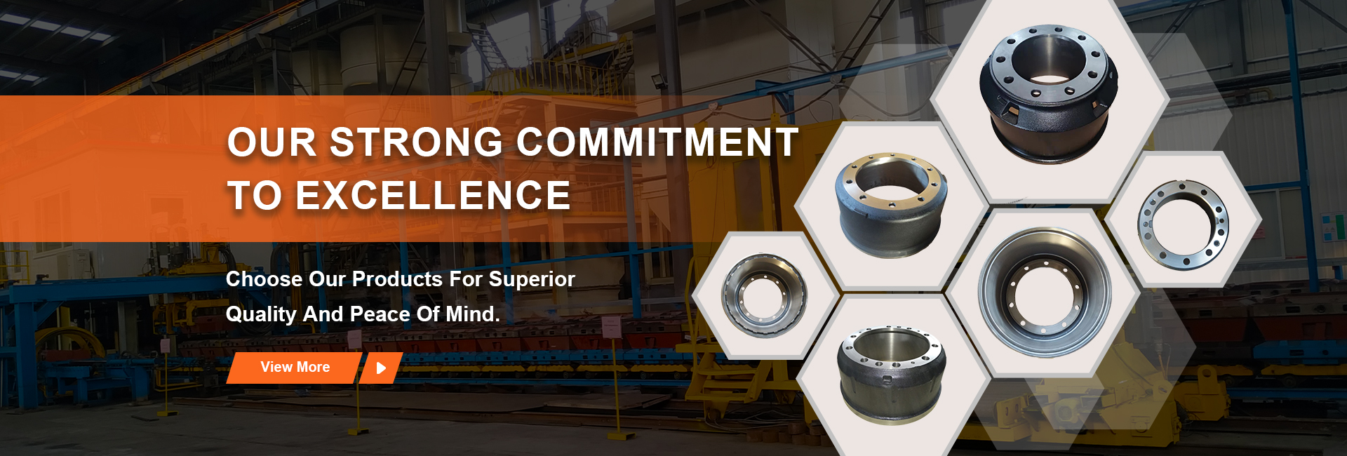
Diagram brake drums are critical components within braking systems, primarily utilized in heavy-duty applications such as commercial vehicles, industrial machinery, and railway systems. Positioned within the vehicle or machine’s drivetrain, the brake drum interfaces with the brake shoes via friction, converting kinetic energy into thermal energy and ultimately decelerating or halting motion. Unlike disc brakes which rely on clamping force applied to a rotating disc, drum brakes utilize an internal expanding shoe system, a design choice influencing their cost-effectiveness and suitability for specific load-bearing applications. Core performance metrics include thermal capacity, frictional stability, wear resistance, and structural integrity under high stress and temperature conditions. The design fundamentally addresses the need for robust and reliable stopping power in demanding operational environments, impacting overall safety and operational efficiency.
Material Science & Manufacturing
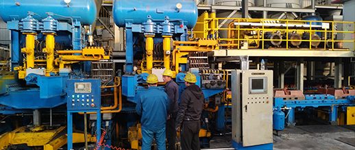
Brake drums are predominantly manufactured from gray cast iron due to its excellent thermal conductivity, wear resistance, and inherent damping characteristics. The chemical composition typically consists of 2.5-4.0% carbon, 1.2-2.5% silicon, 0.3-1.0% manganese, and a low percentage of sulfur and phosphorus. The graphite flake structure within gray cast iron facilitates lubrication during braking, minimizing friction and wear. Alternative materials such as nodular cast iron (ductile iron) are increasingly used for higher performance applications, providing improved strength and toughness. Manufacturing processes commonly involve sand casting, centrifugal casting, and increasingly, near-net shape casting techniques. Sand casting remains prevalent due to its cost-effectiveness for large-scale production, but requires machining operations to achieve precise dimensional tolerances and surface finish. Centrifugal casting yields denser and more uniform castings with improved mechanical properties. Critical parameters during manufacturing include melt temperature, cooling rate, sand composition (for sand casting), and mold design. Precise control of these parameters is essential to minimize defects such as porosity, shrinkage cavities, and residual stresses. Post-casting operations involve machining, heat treatment (stress relieving or surface hardening), and quality control inspections, including dimensional checks, non-destructive testing (NDT) like ultrasonic or magnetic particle inspection, and metallographic analysis to verify microstructure and material properties.
Performance & Engineering
The performance of a brake drum is intrinsically linked to its ability to dissipate heat generated during braking. The thermal capacity of the drum material dictates how much heat can be absorbed before reaching critical temperatures that compromise performance or induce failure. Finite element analysis (FEA) is frequently employed to model thermal stress distribution within the drum during braking events, optimizing design parameters such as drum thickness, fin geometry (for enhanced heat dissipation), and material selection. Force analysis involves calculating the radial and tangential stresses induced by the brake shoes pressing against the drum's inner surface. These stresses are maximized during emergency braking scenarios and must be accounted for in the drum's structural design to prevent cracking or deformation. Environmental resistance is also paramount, with brake drums exposed to corrosive elements like road salt, moisture, and brake fluid. Protective coatings, such as zinc phosphate or powder coating, are often applied to enhance corrosion resistance. Compliance requirements, dictated by industry standards such as FMVSS 105 in the United States and ECE R90 in Europe, specify minimum performance criteria for braking systems, including brake drum specifications related to material composition, dimensional tolerances, and thermal performance. The drum’s geometry directly influences the frictional contact area and the efficiency of heat transfer, requiring careful optimization for specific vehicle or machine applications.
Technical Specifications
| Parameter | Typical Value (Light Duty) | Typical Value (Medium Duty) | Typical Value (Heavy Duty) |
|---|---|---|---|
| Diameter (mm) | 203 | 280 | 320 |
| Width (mm) | 40 | 60 | 80 |
| Material | Gray Cast Iron (Grade 25) | Gray Cast Iron (Grade 30) | Nodular Cast Iron (60-40-18) |
| Tensile Strength (MPa) | 220 | 260 | 400 |
| Thermal Conductivity (W/m·K) | 45 | 48 | 50 |
| Maximum Operating Temperature (°C) | 350 | 400 | 450 |
Failure Mode & Maintenance
Common failure modes in brake drums include thermal cracking, spalling, warping, and excessive wear. Thermal cracking is often initiated by rapid temperature fluctuations during hard braking, creating tensile stresses that exceed the material's strength. Spalling refers to the chipping or flaking of the drum’s surface due to localized stress concentrations and material fatigue. Warping occurs due to uneven heating and cooling, resulting in dimensional distortions that can lead to brake fade and reduced stopping power. Excessive wear is typically caused by abrasive particles embedded in the brake shoes or contamination of the braking surfaces. Fatigue cracking can occur over extended periods of use due to cyclic loading. Failure analysis often involves visual inspection for cracks and wear patterns, metallographic examination to identify material defects, and non-destructive testing to detect subsurface flaws. Preventative maintenance is crucial to maximize brake drum lifespan. This includes regular inspections for wear, cracks, and corrosion; ensuring proper brake shoe adjustment to maintain optimal contact; cleaning the braking surfaces to remove debris and contaminants; and avoiding harsh braking maneuvers that can induce excessive heat. Resurfacing of worn drums is possible, but must be performed within specified limits to maintain structural integrity. Replacing drums showing significant cracking or warping is essential for ensuring braking system safety and performance. Periodic lubrication of the parking brake mechanism is also recommended.
Industry FAQ
Q: What is the primary advantage of using nodular cast iron over gray cast iron in brake drum applications?
A: Nodular cast iron (ductile iron) offers significantly higher tensile strength and toughness compared to gray cast iron. This enhanced mechanical performance allows for thinner drum designs without compromising structural integrity, leading to reduced weight and improved heat dissipation. Nodular cast iron also exhibits better resistance to fatigue cracking, extending the drum's service life in demanding applications.
Q: How does drum brake design account for thermal expansion during braking?
A: Brake drum designs incorporate several features to accommodate thermal expansion. The drums are typically designed with a slight interference fit with the axle to maintain secure mounting even when heated. Fin designs are often optimized to maximize surface area for heat dissipation and minimize thermal stress concentrations. Furthermore, the brake shoe material and adjustment mechanisms are engineered to maintain consistent contact pressure despite drum expansion.
Q: What are the key considerations when selecting a brake drum coating?
A: The primary considerations are corrosion resistance, thermal stability, and compatibility with brake fluids and friction materials. Zinc phosphate coatings provide good corrosion protection at a relatively low cost. Powder coatings offer enhanced durability and resistance to chipping and abrasion. It's crucial to ensure the coating does not interfere with the frictional interface between the drum and the brake shoes.
Q: What are the consequences of ignoring brake drum maintenance?
A: Ignoring brake drum maintenance can lead to reduced braking performance, increased stopping distances, and ultimately, brake failure. Wear and cracks can develop, compromising the drum's structural integrity. Contamination of the braking surfaces can reduce friction and accelerate wear. Regular maintenance is crucial for ensuring safety and preventing costly repairs.
Q: How does the fin geometry of a brake drum influence its performance?
A: The fin geometry directly affects the drum’s heat dissipation capacity. More fins, coupled with optimized fin height and spacing, increase the surface area available for convective heat transfer. The fin design also influences airflow patterns around the drum, enhancing cooling efficiency. Incorrect fin design can lead to localized heat buildup and increased thermal stresses.
Conclusion
Diagram brake drums remain a vital component in numerous braking systems, offering a balance of cost-effectiveness, reliability, and performance. Their enduring utility stems from the inherent properties of cast iron alloys and advancements in manufacturing techniques. Understanding the material science, engineering principles, and potential failure modes is critical for optimizing drum design and ensuring safe and efficient operation.
Future developments in brake drum technology will likely focus on lighter-weight materials, such as composite materials, and improved heat dissipation strategies, potentially incorporating advanced cooling systems. Enhanced predictive maintenance techniques, utilizing sensors and data analytics to monitor drum condition and predict potential failures, will also play an increasingly important role in maximizing service life and minimizing downtime.